Tuesday, June 6, 2017

5/23 Op Amp Relaxation Oscillator

           The purpose of this Lab is to observe how the Rekaxation Oscillator circuit actually works through the experimental method. Then, compare the theoretical value and the experimental value. Analyzes the differences.
Pre- Lab Calculation:
This is the actual set up of our experiment:


1. The following photo is the result of our lab:

Compare to the result from the everycircuit:


Summary 

           In today's class, we learned the concept of oscillator. One important feature of oscillator is that it is able to change the AV current to the DC current which is really important in our daily life.

5/18 No Lab Today

Summary 

    In today's class, we are learning the convert between the frequency and phasor domain. And practice the calculations of these formula. Then, did some example questions.


5/16 Impedance

    The purpose of this lab to find the actual impedance of the circuit through the experiment method. And also observe the effect of the impedance to the circuit.

1. Pre Lab calculation:


2.This is the actual set up of our lab
The following photos are the result of our experiment

100 ohms and 5K Hz and no phase shift

                                                  I = 13.27mA   V = 1.367V


100 ohms and 5K Hz and 32.5 degree phase shift

I = 34mA     V = 1.06V


100 ohms and 5K Hz and 82.8 degree phase shift


I = 6.2mA    V = 2.05V

Summary 
     In today's class, we are introduced the concept of impedance. We can calculate the impedance of capacity and inductor. Then, trade them as resistance.

Monday, June 5, 2017

5/11 Phasors: Passive RL Circuit Response

         The purpose of this lab is to observe the unique function of passive RL circuit. We need to know how to calculate in the phasor domain

Pre lab:
These are the calculations we did for this lab.

The cutoff frequency for 1mH and 470Ohm resistor is 47000/2Pi = 7480Hz
The frequency with one tenth of cutoff frequency is 748Hz
The frequency with ten times of cutoff frequency is 74800Hz


This is the actual set up of our experiment.

The following photos are the result of our lab

1. the phase difference is (3.102)/(13.5)*360 = -82.72degree,

2. the phase difference is (16.87)/(135)*360 = -44.9degree,
3. the phase difference is (0.03)/1.45 = -7.448degree,

summary
    In today's class ,we learned how to convert the time domain to the phasor domain. Then, we can do the futher calculation.The following are some rule of the converting:


5/9 RLC Circuit Response

1. Provide the differential equation governing the circuit.

2. Attach plots of the input step function you applied to the circuit and the resulting circuit step response.


3. Provide the damping ratio, DC gain and natural frequency.
damping ratio:0.25
DC gain: 8
Natural frequency:  10105.8 Hz

4. Compare your measured vs expected parameters
They are pretty close.

Summary
    In today's class, we keeping learning the concept of RLC circuit. There are two different types of RLC circuit one is parallel and the other one is series. Different RLC have different equation to do the calculation.

5/2 Series RLC Circuit Step Response

          The purpose of this lab is to find the DC gain and phase shift through the experimental method. Then, compare with the theoretical value we calculated in the pre-lab

1. Provide the differential equation governing the circuit.
2. Attach, plots of the input step function you applied to the circuit and the resulting circuit step response.
According to the picture, raise time: 1.241ms
overshoot:3.5ms
oscillation frequency: 23485Hz

3. Provide the estimate of the damping ratio, natural frequency, DC gain, and damped natural               frequency.
damping ratio: 5*10^-7
DC Gain: 2.383

Summary
    In today's class we learned how to calculate Series RLC Circuit. We learned the formula to calculate the w and α. Then use those data to calculate the current and voltage.

4/25 Inverting Differentiator

        The purpose of this lab is to verify the function of inverting differentiator. We need to find the out voltage and input voltage through the experiment. Then, compare these values with the theoretical value.

1. Provide the input-output relation  for the circuit:
 the relation is showed in the photo.

2. Provide a schematic of the circuit you implemented:

The actual resistance we used in the lab is 665

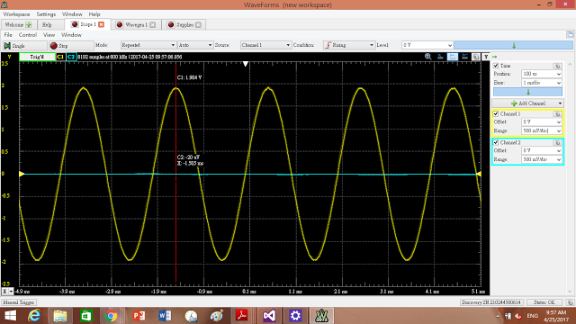
3. Attach an image of the oscilloscope window for the 100 HZ sinusoidal input:

4. Attach an image of the oscilloscope window for the 250 HZ sinusoidal input

5. Attach an image of the oscilloscope window for the 500Hz sinusoidal input 

6. Provide a table showing the expected output voltage amplitudes


Summary
               In today's class, we introduce the definition of differentiator. A  differentiator is a circuit that is designed such that the output of the circuit is approximately directly proportional to the rate of change (the time derivative) of the input. An active differentiator includes some form of amplifier. A passive differentiator circuit is made of only resistors and capacitors.